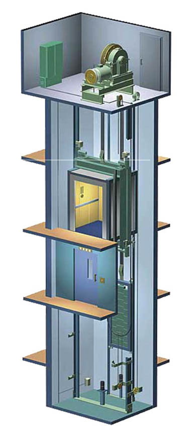
OHT Car Type Summary
This design utilizes a geared traction machine, along with the controller and governor, mounted in a penthouse machine room directly above the hoistway. This application uses hoist ropes and counterweight to move the car, in lieu of a hydraulic jack. The counterweights can be positioned at the rear of the car (front open only), or at the side of the car. In addition to the main rails, a set of counterweight frame rails are also required.
Advantages
Advantages to using this design include a much faster speed capability, an unlimited travel range and a higher power efficiency than hydraulic car types. In addition, there is no hydraulic oil being used.
Disadvantages
Disadvantages include a substantially higher material cost than hydraulic car types, along with a higher field installation cost. In addition, a higher OH is required (typically 16ft) along with a penthouse machine located over the hoistway.
The penthouse machine room can be eliminated by positioning the geared machine next to the side of the hoistway at one of the landings. This arrangement is referred to as a basement machine application, also requiring additional hoistway sheaves and machine beam support at the landing location of the machine.
| Capacity (lbs.) | Openings F=Front R=Rear | Door Type and Width | Platform Size W x D | Max Speed FPM | Hoistway Size W x D | Clear Inside W x D | Minimum Overhead | Minimum Pit Depth |
|---|---|---|---|---|---|---|---|---|
| Counterweight at REAR | ||||||||
| 2100 | F | 1SP 36” | 6’-0” x 5’-1” | 350 | 7’-4” x 6’-7 ½” | 5’-8” x 4’-3” | 16’-0” | 5’-2” |
| 2500 | F | 1SP 42” | 7’-0” x 5’-1” | 350 | 8’-4” x 6’-7 ½” | 5’-8” x 4’-3” | 16’-0” | 5’-2” |
| 3000 | F | 1SP 42” | 7’-0” x 5’-6” | 350 | 8’-4” x 7’-0 ½” | 6’-8” x 4’-8” | 16’-0” | 5’-2” |
| 3500 | F | 1SP 42” | 7’-0” x 6’-2” | 350 | 8’-4” x 7’-8 ½” | 6’-8” x 5’-4” | 16’-0” | 5’-2” |
| 4000 | F | 1SP 48” | 8’-0” x 6’-2” | 350 | 9’-4” x 7’-8 ½” | 7’-8” x 5’-4” | 16’-0” | 5’-2” |
| Counterweight at SIDE | ||||||||
| 2100 | F | 1SP 36” | 6’-0” x 5’-1” | 350 | 7’-10” x 5’-9” | 5’-8” x 4’-3” | 16’-0” | 5’-2” |
| 2500 | F | 1SP 42” | 7’-0” x 5’-1” | 350 | 8’-10” x 5’-9” | 6’-8” x 4’-3” | 16’-0” | 5’-2” |
| 3000 | F | 1SP 42” | 7’-0” x 5’-6” | 350 | 8’-10” x 6’-2” | 6’-8” x 4’-8” | 16’-0” | 5’-2” |
| 3500 | F | 1SP 42” | 7’-0” x 6’-2” | 350 | 8’-10” x 6’-10” | 6’-8” x 5’-4” | 16’-0” | 5’-2” |
| 3500 | F&R | 1SP 42” | 7’-0” x 6’-9” | 350 | 8’-10” x 7’-9 ½” | 6’-8” x 5’-5” | 16’-0” | 5’-2” |
| 4000 | F | 1SP 48” | 8’-0” x 6’-2” | 350 | 9’-10” x 6’-10” | 7’-8” x 5’-4” | 16’-0” | 5’-2” |
| 4000 | F&R | 1SP 48” | 8’-0” x 6’-8” | 350 | 9’-10” x 7’-8 ½” | 7’-8” x 5’-4” | 16’-0” | 5’-2” |
| 3500H | F | 2SP 42” | 5’-4” x 8’-4” | 350 | 7’-2” x 9’-2” | 5’-0” x 7’-4” | 16’-0” | 5’-2” |
| 3500H | F | 2SP 42” | 5’-4” x 9’-0 ½” | 350 | 7’-2” x 10’-4” | 5’-0” x 7’-4 ½” | 16’-0” | 5’-2” |
| 4000H | F | 2SP 48” | 6’-0” x 8’-5” | 350 | 7’-10” x 9’-3” | 5’-8” x 7’-5” | 16’-0” | 5’-2” |
| 4000H | F&R | 2SP 48” | 6’-0” x 9’-1 ½” | 350 | 7’-10” x 10’-5” | 5’-8” x 7’-5 ½” | 16’-0” | 5’-2” |
| 4500H | F | 2SP 48” | 6’-0” x 9’-2” | 350 | 7’-10” x 10’-0” | 5’-8” x 8’-2” | 16’-0” | 5’-2” |
| 4500H | F&R | 2SP 48” | 6’-0” x 9’-10 ½” | 350 | 7’-10” x 11’-2” | 5’-8” x 8’-2 ½” | 16’-0” | 5’-2” |
| 5000H | F | 2SP 48” | 6’-0” x 9’-7 ½” | 350 | 7’-10” x 10’-5 ½” | 5’-8” x 8’-7 ½” | 16’-6” | 5’-2” |
| 5000H | F&R | 2SP 48” | 6’-0” x 10’-3 ½” | 350 | 7’-10” x 11’-7” | 5’-8” x 8’-7 ½” | 16’-6” | 5’-2” |
Based on car speed of 200 FPM Cab Height = 8’-0”
For seismic applications add 3” to hoistway width.
Speeds exceeding 200 FPM require additional overhead and pit depth. Minimum pit depth is based on the use of spring buffers. Add 5” to pit depth if oil buffers are required or car speed exceeds 200 FPM.
225 FPM = add 6” of overhead and 5” of pit depth 250 FPM = add 7” of overhead and 5” of pit depth 300 FPM = add 8” of overhead and 5” of pit depth 350 FPM = add 10” of overhead and 5” of pit depth
Hoistway dimensions are not for final construction purposes. National & local code years & variations may affect sizes shown. All dimensions should be verified with Delaware Elevator prior to construction.
DEM can provide not only standard sizes as outlined above but also non-standard or custom sizes. Please consult DEM for details.