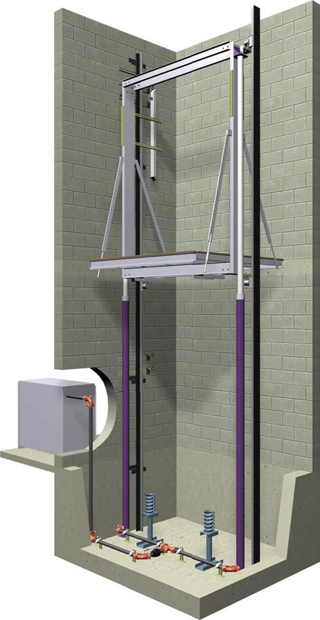
TWIN JACK HOLELESS CAR
TYPE SUMMARY
This design uses (2) jacks, one on each side of the car, positioned between the platform and the hoistway wall. Single stage jacks are used for low travel, typically on 2 stop cars up to 14 ft. Two stage jacks are used for travel up to 28 to 30 feet (typically 3 to 4 stops).
Advantages
The jacks are located above ground, thereby eliminating the need to drill a jack hole and eliminating the risk of oil contamination. This car type will also accommodate low and high capacity cars.
Disadvantages
Travel is typically restricted to a 2 to 4 stop application. Depending upon the travel, an extended overhead may be required to fit the jacks into the hoistway elevation. The hoistway width requirement may also be a little greater than an in-ground car type, for high capacity applications.
| Capacity (lbs.) | Openings F=Front R=Rear | Door Type and Width | Platform Size W(C) X D(D) | Hoistway Depth Platform Plus | Hoistway Size W(A) X D(B) | Clear Inside W X D | Running Clearance Sill/Plat | Sill Depth Req'd' | DOWNLOADS | |
|---|---|---|---|---|---|---|---|---|---|---|
| 2100 | F | 1-SP 36" | 6'-0" X 5'-1" | 9" | 7'-4" X 5'-10" | 5'-8" X 4'-3" | 1" | 5" | DWG | |
| 2100 | F&R | 1-SP 36" | 6'-0" X 5'-8" | 12" | 7'-4" X 6'-8" | 5'-8" X 4'-4" | 1" | 5" | DWG | |
| 2500 | F | 1-SP 42" | 7'-0" X 5'-1" | 9" | 8'-4" X 5'-10" | 6'-8" X 4'-3" | 1" | 5" | DWG | |
| 2500 | F&R | 1-SP 42" | 7'-0" X 5'-8" | 12" | 8'-4" X 6'-8" | 8'-8" X 4'-4" | 1" | 5" | DWG | |
| 3000 | F | 1-SP 42" | 7'-0" X 5'-6" | 9" | 8'-4" X 6'-3" | 6'-8" X 4'-8" | 1" | 5" | DWG | |
| 3000 | F&R | 1-SP 42" | 7'-0" X 5'-11" | 12" | 8'-4" X 6'-11" | 6'-8" X 4'-7" | 1" | 5" | DWG | |
| 3500 | F | 1-SP 42" | 7'-0" X 6'-3" | 9" | 8'-4" X 7' | 6'-8" X 5'-5" | 1" | 5" | DWG | |
| 3500 | F&R | 1-SP 42" | 7'-0" X 6'-9" | 12" | 8'-4" X 7'-9" | 6'-8" X 5'-5" | 1" | 5" | DWG | |
| 3500H | F | 2-SP 42" | 5'-4" X 8'-4" | 11" | 6'-8" X 9'-3" | 5'-0" X 7'-4" | 1" | 6½" | DWG | |
| 3500H | F&R | 2-SP 42" | 5'-4" X 9'-0" | 15" | 6'-8" X 10'-3" | 5'-0" X 7'-4" | 1" | 6½" | DWG | |
| 4000 | F | 1-SP 48" | 8'-0" X 6'-3" | 9" | 9'-4" X 7' | 7'-8" X 5'-5" | 1" | 5" | DWG | |
| 4000 | F&R | 1-SP 48" | 8'-0" X 6'-9" | 12" | 9'-4" X 7'-9" | 7'-8" X 5'-5" | 1" | 5" | DWG | |
| 4000H | F | 2-SP 48" | 6'-0" X 8'-5" | 11" | 7'-4" X 9'-3" | 5'-8" X 7'-5" | 1" | 6½" | DWG | |
| 4000H | F&R | 2-SP 48" | 6'-0" X 9'-1" | 15" | 7'-4" X 10'-4" | 5'-8" X 7'-5" | 1" | 6½" | DWG | |
| 4500H | F | 2-SP 48" | 6'-0" X 8'-9" | 11" | 7'-4" X 9'-7" | 5'-8" X 7'-9" | 1" | 6½" | DWG | |
| 4500H | F&R | 2-SP 48" | 6'-0" X 9'-6" | 15" | 7'-4" X 10'-9" | 5'-8" X 7'-10" | 1" | 6½" | DWG | |
| 5000H | F | 2-SP 48" | 6'-0" X 9'-8" | 11" | 7'-6" X 10'-7" | 5'-8" X 8'-8" | 1" | 6½" | DWG | |
| 5000H | F&R | 2-SP 48" | 6'-0" X 10'-4" | 15" | 7'-6" X 11'-7" | 5'-8" X 8'-8" | 1" | 6½" | DWG | |
OVERHEAD REQUIRED QUICK CALCULATION
Regardless of what the travel is, the standard mimimum overhead is 12′-6″. Consult your Delaware Elevator representative if your overhead is less than 12′-6″. For every 1″ of travel over 12′-0″ either the overhead or the pit depth must be increased by a corresponding 1″.
| Pit Depth | 4'-0" |
| Piston Bottom Undertravel | 9" |
| Car Speed | Up To 150 FPM |
| Cab Height | 8'-0" |
| Piston Top Overtravel | 5" |
MAXIMUM INSIDE NET PLATFORM AREAS
To allow for variations in cab designs, an increase in the maximum inside net platform area not exceeding 5% shall be permitted for the various capacity loads.
| Rated Capacity (Lbs.) | Inside Net Area (Sq. Ft.) |
|---|---|
| 2100 | 24.2 |
| 2500 | 29.1 |
| 3000 | 33.7 |
| 3500 | 38.0 |
| 4000 | 42.2 |
| 4500 | 46.2 |
| 5000 | 50.0 |
APPROXIMATE CLEAR INSIDE DIMENSIONS OF CAB
Width = Platform Width less 4″
Depth = Front Open Only
· SSSO & CO Doors = Platform Depth Less 10″
· 2SSO Doors = Platform Depth less 12″
Depth = Front & Rear Open
· SSSO & CO Doors = Platform Depth Less 16″
· 2SSO Doors = Platform Depth less 20″
DBG (Distance Between Guides) = Platform Width plus 3 1/4″ 15# rail depth= 3 1/2″
RAIL BRACKET FASTENING TO HOISTWAY WALLS
Hoistway wall supports for rail bracket fastening are required per the layout drawing locations. For block or masonary walls, wall inserts must be installed in the walls by OTHER than the Elevator Contractor. Masonary block must be filled with mortar around wall inserts to provide a solid permanent rail bracket support.
For wood and metal stud hoistway walls, covered with sheetrock, a suitable header support (running front-to-back on each hoistway side wall) is required at each rail bracket location, as per the rail force and location shown on the job specific layout drawing.
OVERHEAD REQUIRED - QUICK CALCULATIONS
SINGLE STAGE JACKS
UP to 100 FPM:
Pit Depth = 4’-0”
Overhead = 12’-6”
Top Over Travel = 3.5”
Bottom Over Travel = 5.0”
Max. Travel = 13’-10”
Max. “Overall” Cab Height = 8’-6”
101-125 FPM:
Pit Depth = 4’-0”
Overhead = 12’-6”
Top Over Travel = 4.25”
Bottom Over Travel = 7.25”
Max. Travel = 13’-4”
Max. “Overall” Cab Height = 8’-6”
TWO STAGE JACKS
UP to 100 FPM:
Pit Depth = 4’-0”
Overhead = 12’-6”
Top Over Travel = 7.5”
Bottom Over Travel = 5.5”
Max. Travel = 24’-4”
Max. “Overall” Cab Height = 8’-2”
101-125 FPM:
Pit Depth = 4’-0”
Overhead = 12’-6”
Top Over Travel = 9.0”
Bottom Over Travel = 7.0”
Max. Travel = 24’-4”
Max. “Overall” Cab Height = 8’-2”
APPROXIMATE CLEAR INSIDE DIMENSIONS OF CAB
Width = Platform Width less 4″
Depth = Front Open Only
· SSSO & CO Doors = Platform Depth Less 10″
· 2SSO Doors = Platform Depth less 12″
Depth = Front & Rear Open
· SSSO & CO Doors = Platform Depth Less 16″
· 2SSO Doors = Platform Depth less 20″
DBG (Distance Between Guides) = Platform Width plus 3 1/4″ 15# rail depth= 3 1/2″