In-Ground Car Type Summary
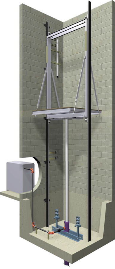
This is the traditional elevator application that has been used for many years. The jack is located directly under the platform in the ground and is protected from the ground using a PVC liner.
Advantages
Material cost for this package is less expensive than all other car types. The package is the easiest to install and is available in both low and high capacity applications. Heavy freight cars are typically always in-ground. The pit depth and overhead dimensions are typically always standard, not requiring any extended dimensions – even though the travel can be upwards to several landings.
Disadvantages
Jack is located underground and oil contamination is remotely possible. The PVC liner provides protection between the cylinder and the actual soil. Geographic areas which experience seismic activity will present the greatest risk of oil contamination. The jack (single stage) must go down into the ground the same distance as the travel. Drilling a jack hole can be expensive depending upon ground conditions.
| Capacity (lbs.) | Openings F=Front R=Rear | Door Type and Width | Platform Size W x D | Hoistway Depth Platform Plus | Hoistway Size W x D | Clear Inside W x D | Running Clearance Sill/Plat | Sill Depth Req’d’ | DOWNLOADS | |
|---|---|---|---|---|---|---|---|---|---|---|
| 2100 | F | 1SP 36” | 6’-0” x 5’-1” | 9” | 7’-4” x 5’-10” | 5’-8” x 4’-3” | 1” | 5” | DWG | |
| 2100 | F&R | 1SP 36” | 6’-0” x 5’-8” | 12” | 7’-4” x 6’-8” | 5’-8” x 4’-4” | 1” | 5” | DWG | |
| 2500 | F | 1SP 42” | 7’-0” x 5’-1” | 9” | 8’-4” x 5’-10” | 6’-8” x 4’-3” | 1” | 5” | DWG | |
| 2500 | F&R | 1SP 42” | 7’-0” x 5’-8” | 12” | 8’-4” x 6’-8” | 6’-8” x 4’-4” | 1” | 5” | DWG | |
| 3000 | F | 1SP 42” | 7’-0” x 5’-6” | 9” | 8’-4” x 6’-3” | 6’-8” x 4’-8” | 1” | 5” | DWG | |
| 3000 | F&R | 1SP 42” | 7’-0” x 5’-11” | 12” | 8’-4” x 6’-11” | 6’-8” x 4’-7” | 1” | 5” | DWG | |
| 3500 | F | 1SP 42” | 7’-0” x 6’-3” | 9” | 8’-4” x 7’-0” | 6’-8” x 5’-5” | 1” | 5” | DWG | |
| 3500 | F&R | 1SP 42” | 7’-0” x 6’-9” | 12” | 8’-4” x 7’-9” | 6’-8” x 5’-5” | 1” | 5” | DWG | |
| 3500H | F | 2SP 42” | 5’-4” x 8’-4” | 11” | 6’-8” x 9’-3” | 5’-0” x 7’-4” | 1” | 6 ½” | DWG | |
| 3500H | F&R | 2SP 42” | 5’-4” x 9’-0” | 15” | 6’-8” x 10’-3” | 5’-0” x 7’-4” | 1” | 6 ½” | DWG | |
| 4000 | F | 1SP 48” | 8’-0” x 6’-3” | 9” | 9’-4” x 7'-0” | 7’-8” x 5’-5” | 1” | 5” | DWG | |
| 4000 | F&R | 1SP 48” | 8’-0” x 6’-9” | 12” | 9’-4” x 7’-9” | 7’-8” x 5’-5” | 1” | 5” | DWG | |
| 4000H | F | 2SP 48” | 6’-0” x 8’-5” | 11” | 7’-4” x 9’-3” | 5’-8” x 7’-5” | 1” | 6 ½” | DWG | |
| 4000H | F&R | 2SP 48” | 6’-0” x 9’-1” | 15” | 7’-4” x 10’-4” | 5’-8” x 7’-5” | 1” | 6 ½” | DWG | |
| 4500H | F | 2SP 48” | 6’-0” x 8’-9” | 11” | 7’-4” x 9’-7” | 5’-8” x 7’-9” | 1” | 6 ½” | DWG | |
| 4500H | F&R | 2SP 48” | 6’-0” x 9’-6” | 15” | 7’-4” x 10’-9” | 5’-8” x 7’-10” | 1” | 6 ½” | DWG | |
| 5000H | F | 2SP 48” | 6’-0” x 9’-8” | 11” | 7’-6” x 10’-7” | 5’-8” x 8’-8” | 1” | 6 ½” | DWG | |
| 5000H | F&R | 2SP 48” | 6’-0” x 10’-4” | 15” | 7’-6” x 11’-7” | 5’-8” x 8’-8” | 1” | 6 ½” | DWG | |
APPROXIMATE CLEAR INSIDE DIMENSIONS OF CAB
Width = Platform Width less 4”
Depth = Front Open Only
SSSO & CO Doors = Platform Depth Less 10” 2SSO Doors = Platform Depth less 12”
Depth = Front & Rear Open
SSSO & CO Doors = Platform Depth Less 16” 2SSO Doors = Platform Depth less 20”
DBG (Distance Between Guides)
Platform Width plus 3 ¼” 12# / 15# rail depth= 3 ½”
OVERHEAD REQUIRED QUICK CALCULATION
Regardless of what the travel is, the standard minimum overhead is 12’-6”. Consult your Delaware Elevator representative if your overhead is less than 12’-6”.
| Pit Depth | 4’-0” |
| Piston Bottom Under-travel | 12” |
| Car Speed | Up To 150 FPM |
| Cab Height | 8’-0” |
| Piston Top Over-travel | 5 |
DEM can provide not only standard sizes as outlined above but also non-standard or custom sizes. Please consult DEM for details.